October 15, 2026
Eliminating A-Surface Scratches: Non-Marring Anti-Static Co-Extrusions for Painted Automotive Trim Trays
1. Introduction: The Scratch That Costs More Than the Part
I have been working in automotive interior materials specification for over a decade, and I can tell you that the most expensive defect in a paint shop is not a paint defect. It is a scratch on a painted A-surface that was caused by the tray that carried the part.
Here is the scenario. A painted trim component – a door handle bezel, a console trim strip, a pillar cover – comes out of the paint booth with a flawless Class A finish. It is placed into a returnable transport tray for movement to the assembly line. The tray is made from standard polypropylene or ABS. The part shifts slightly during transport. The tray surface contacts the painted surface. And when the part arrives at assembly, there is a hairline scratch across the visible surface that no amount of polishing will remove.
The part is scrapped. The paint shop reworks it. The assembly line waits. And the cost of that single scratch – in labor, material, and schedule disruption – is ten to a hundred times the cost of the tray that caused it.
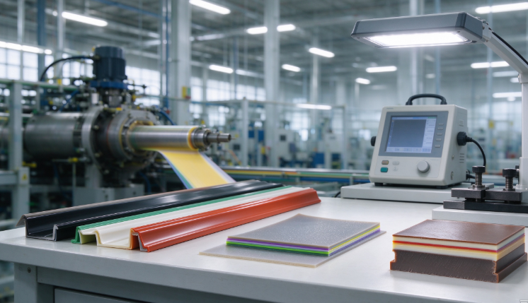
The automotive industry’s answer to this problem is a non-marring, anti-static co-extruded sheet that forms the tray surface. The co-extrusion structure places a soft, low-friction skin on the part-contact surface while keeping a rigid, cost-effective core for structural integrity. The anti-static additive prevents electrostatic charge buildup that attracts dust and can discharge into sensitive electronic components. And the whole system eliminates the need for separate protective liners, felt pads, or coating steps that add cost and complexity.
This is not a theoretical solution. The co-extrusion technology is mature, the material formulations are commercially available, and the cost data from documented case studies shows that the transition from single-layer to multi-layer co-extrusion can reduce total tray cost by 30% while simultaneously improving surface protection.
2. Why Trim Trays Scratch Painted A-Surfaces
To understand why co-extrusion solves the problem, you first need to understand the mechanism of scratch formation on a painted A-surface.
Mechanism 1: Hard particle entrapment. Dust and debris particles settle on tray surfaces in the paint shop environment. When a painted part contacts the tray, these particles are pressed into the paint surface, creating scratches that follow the direction of relative movement. The scratch depth depends on the hardness of the particle relative to the paint clearcoat.
Mechanism 2: Adhesive friction. Standard polypropylene and ABS have relatively high coefficients of friction against automotive clearcoat. When the part shifts during transport, the friction between the tray surface and the painted surface generates shear forces that can exceed the scratch resistance of the clearcoat. The result is a mar or scuff that is visible under oblique lighting.
Mechanism 3: Static-attracted contamination. Electrostatic charge builds on the tray surface as it moves through the paint shop – a dry, low-humidity environment that is ideal for charge accumulation. This charge attracts dust particles, increasing the concentration of abrasive particles at the tray-part interface. Static discharge can also damage sensitive electronic components that may be present on or near painted trim assemblies.
Mechanism 4: Surface roughness transfer. Standard injection-molded or thermoformed tray surfaces have a surface roughness (Ra) that can range from 0.5 to 2.0 micrometers. Under contact pressure, the asperities on the tray surface can imprint onto soft paint finishes, particularly on freshly painted parts that have not fully cured.
The co-extrusion solution addresses all four mechanisms simultaneously. The non-marring skin provides a low-friction, smooth surface that resists particle entrapment and reduces adhesive friction. The anti-static additive eliminates charge accumulation and the contamination it attracts.
3. How Co-Extrusion Solves Both Problems at Once
Co-extrusion is a manufacturing process in which two or more polymer melts are combined in a single die to produce a multi-layer sheet or profile. Each layer can have a different composition, thickness, and function.
For a painted trim tray, the typical co-extrusion architecture uses a three-layer structure: a non-marring skin layer on the part-contact surface, a structural core layer, and an anti-static layer on the tray surface or as a functional additive in the core.
The anti-static sheet patent literature describes a preferred thickness ratio for a three-layer construction: outer layer 0.01–0.50 mm, core layer 0.50–1.00 mm, outer layer 0.01–0.50 mm. For automotive trays, the total sheet thickness typically ranges from 1.5 to 4 mm, with thicker sheets and reinforced ribs recommended for heavy loads or repeated stacking.
The key to co-extrusion performance is interface adhesion. The patent notes that it is preferred for the thermoplastic resin in the core layer and the outer layer to be the same polymer family, ensuring strong adhesion between layers during co-extrusion. When the resins are compatible, the layers bond during the melt phase and form a unified sheet that will not delaminate during thermoforming, transport, or cleaning.
The manufacturing process is straightforward. Two or more extruders feed molten polymer into a feed block, which distributes the melts into the desired layer configuration. The combined melt stream passes through a die that shapes it into a sheet. The sheet is cooled on casting rolls and wound for shipment. For trays, the sheet is subsequently thermoformed – heated and vacuum-drawn over a mold – to create the tray geometry with the non-marring skin on the cavity side and the structural core providing rigidity.
Layer | Function | Typical Material | Thickness Range |
Skin (part-contact) | Non-marring, low friction | TPE, POE-modified PP, soft-touch ABS | 0.01–0.50 mm |
Core (structural) | Rigidity, dimensional stability | PP + talc, ABS, HIPS + carbon black | 0.50–4.00 mm |
Anti-static (functional) | Static dissipation | PP/ABS with antistatic masterbatch or carbon black | Distributed or surface layer |
Sources: Patent US20060235154, CANDEA Plastics, industry data
4. The Anti-Static Layer: Surface Resistivity Targets and Additive Chemistry
Anti-static performance in a co-extruded tray is measured by surface resistivity – the resistance to electrical current flowing across the surface of the material. The target range depends on the application.
For automotive paint shop trays that handle painted trim and may encounter sensitive electronic components, the appropriate range is 10⁸ to 10¹¹ Ω/sq for dissipative materials and 10³ to 10⁶ Ω/sq for conductive materials. The ESD-safe tray standard ANSI/ESD S20.20 requires surface resistivity below 10⁶ Ω/sq for conductive trays and below 10¹¹ Ω/sq for dissipative trays.
There are two main chemistries for achieving anti-static performance in polyolefin-based trays.
Internal antistatic agents are compounded into the polymer melt. The PELECTRON LIP antistatic agent from Sanyo Chemical is an internal antistatic agent based on glycerol ester derivatives, supplied as pellets for compounding into PP and HDPE. It is non-migrating, thermally stable up to 280°C, and halogen-free, making it suitable for high-temperature processing and compliance with RoHS and REACH. The recommended loading level is 0.5–2.0 wt% depending on the substrate and performance requirements.
Conductive carbon black is used for lower resistivity ranges. PRE-ELEC PS 1340 is a conductive thermoplastic concentrate based on polystyrene with a high concentration of special conductive carbon black, designed for mono- or co-extruded sheets for thermoformed trays. Conductive antistatic PP with carbon black achieves surface resistance in the range of 10³ to 10⁵ Ω, making it suitable for anti-static IC trays, turnover boxes, and automotive parts.
Permanent vs. migratory. The critical selection criterion for automotive trays is whether the anti-static mechanism is permanent or migratory. Migratory antistatic agents bloom to the surface over time and are gradually removed by cleaning and handling. Non-migrating additives, such as the PELECTRON LIP type or inherently conductive carbon black networks, maintain their performance throughout the product lifecycle. CANDEA Plastics specifies that their ESD materials provide "constant electrostatic performance throughout the entire product lifecycle" – a requirement that migratory systems cannot meet.
Avient’s OnFlex thermoformable TPEs combine anti-static performance with soft-touch finish and non-slip properties (CoF > 0.5), achieving a non-migrating surface resistivity of 10¹⁰ Ω/sq. These materials are specifically designed for vehicle interior trim parts and industrial safety applications.
Anti-Static Technology | Surface Resistivity | Mechanism | Permanence |
Internal antistatic agent (glycerol ester) | 10⁸–10¹¹ Ω/sq | Migratory to surface | Non-migrating grades available |
Conductive carbon black | 10³–10⁶ Ω/sq | Conductive network | Permanent |
Conductive carbon black concentrate | 10³–10⁸ Ω/sq | Diluted in core or skin | Permanent |
Inherently dissipative polymer | 10⁸–10¹¹ Ω/sq | Polymer chain conductivity | Permanent |
5. The Non-Marring Skin: Scratch Resistance Mechanisms and Material Selection
The non-marring skin layer is what prevents the tray from scratching the painted part. Its performance depends on three material properties: coefficient of friction, surface smoothness, and hardness.
Coefficient of friction (CoF) determines the shear force that develops when the part shifts against the tray. A lower CoF means less scratch-inducing force at the interface. Avient’s OnFlex TPEs achieve a CoF > 0.5, which provides grip for the part while remaining low enough to prevent scuffing.
Surface smoothness determines whether the tray surface has asperities that can imprint onto the paint. The POE-modified skin layer in the five-layer co-extrusion case study delivered a smooth, paintable surface that met OEM appearance standards.
Hardness affects how the tray surface deforms under contact. A softer skin deforms elastically and distributes contact pressure over a larger area, reducing the peak stress on the paint surface. TPE-H-ABS ESD Soft-Touch CA-572 combines rubber-like haptics with ABS impact strength, providing a soft-touch surface that is both ergonomic and non-marring.
For scratch resistance in the core structural layer, WACKER’s GENIOPLAST PP50S12 is a pelletized masterbatch containing 50% ultra-high molecular weight silicone gum dispersed in polypropylene homopolymer. Adding 2% GENIOPLAST PP50S12 to a 20% talc-filled PP compound reduces the scratch visibility (ΔL) from 5.3 to 0.9 after an Erichsen scratch test. The lower ΔL value means less light scattering from the scratch, which gives the appearance of a less severely damaged surface. The dosage range is 1–3%, and the benefits include improved scratch and mar resistance, reduced scratch visibility, and no tackiness or fogging.
Javachem’s HG series surface modifiers provide scratch resistance, no stickiness, low VOC, and low stress whitening for dashboard, door trim, center console, pillar trim, and other PP and TPO auto-body parts.
Skin Layer Material | CoF | Key Property | Application |
POE-modified PP | Moderate | Smooth, paintable surface | Paint shop trays, door panels |
TPE-H-ABS soft-touch | >0.5 | Rubber-like haptics + ABS toughness | Trim trays, interior components |
TPU-based soft-touch | Low | Abrasion resistance, chemical resistance | High-wear trays |
PP + GENIOPLAST PP50S12 | Reduced | ΔL reduced from 5.3 to 0.9 | Core layer scratch resistance |
6. Head-to-Head: Co-Extruded vs. Single-Layer vs. Coated Trays
Parameter | Co-Extruded Tray | Single-Layer Tray | Coated/Lined Tray |
Scratch resistance | Excellent — low-friction skin | Poor — hard surface scratches paint | Good — coating protects |
Anti-static performance | Integrated in skin/core | Requires additive in bulk | Coating may dissipate over time |
Layer adhesion | Excellent — melt-bonded | N/A | Coating can delaminate |
Thermoformability | Good — layers bond during forming | Excellent | Limited — coating may crack |
Cost per part | Moderate | Low | High — extra step, labor, materials |
Weight | Low | Lowest | Higher — coating adds weight |
Recyclability | Good — compatible polymers | Good | Poor — coating contaminates recycle stream |
Cleaning durability | Good — integrated properties | N/A | Coating wears with cleaning |
Lamination step | Eliminated | Required for aesthetics | N/A — coating is the step |
7. Design Parameters That Determine Co-Extrusion Performance
Getting the co-extrusion right requires attention to several design parameters that affect both the manufacturing process and the end-use performance.
Layer thickness ratio determines the balance between surface performance and structural cost. A thicker skin layer provides more scratch protection but increases material cost. A thinner skin reduces cost but may wear through. The patent-specified range of 0.01–0.50 mm for the outer layer provides a practical starting point, but the optimal thickness depends on the tray's contact pressure and handling frequency.
Interface adhesion is the single most important manufacturing parameter. If the layers do not bond properly, the skin can delaminate during thermoforming or service. The patent recommends using the same thermoplastic resin family for the core and outer layers to ensure adhesion. When different resins are used, compatibility testing is essential.
Sheet thickness for automotive trays typically ranges from 1.5 to 4 mm, with thicker sheets and reinforced ribs recommended for heavy loads or repeated stacking.
Anti-static loading level determines the surface resistivity. For dissipative performance (10⁸–10¹¹ Ω/sq), the antistatic agent loading is typically 0.5–2.0 wt%. For conductive performance (10³–10⁶ Ω/sq), carbon black loading is significantly higher and may require a dedicated conductive layer rather than a bulk additive.
Thermoforming compatibility must be verified. The co-extruded sheet must maintain layer integrity through the heating, stretching, and cooling cycles of thermoforming. The POE-modified skin in the case study was specifically selected to provide a smooth surface that survives thermoforming without cracking or delaminating.
8. Case Study: Tier 1 Supplier Achieves 30% Cost Reduction with Multi-Layer Co-Extrusion
The most instructive documented case study for co-extrusion economics comes from a Tier 1 automotive interior components supplier producing door panel substrates for a German luxury vehicle program.
The challenge. The supplier’s legacy process used single-layer mineral-filled polypropylene sheet with 30% talc loading to achieve the required stiffness. Virgin PP resin was the largest cost line item, and escalating resin prices eroded margins to break-even. The talc-filled surface also required a separate lamination step to apply a textile or PVC skin, adding 12% to total component manufacturing time plus labor, adhesive, and equipment depreciation.
The solution. The supplier implemented a 5-layer A/B/C/B/A co-extrusion line that replaced the single-layer process. The configuration placed recycled PP (30% post-industrial content) in the core layer, flanked by mineral-filled PP structural layers with 35% talc loading, and POE-modified PP skin layers on both surfaces.
The results. The recycled core reduced virgin resin consumption by 22%. The multi-layer structure eliminated the need for a separate lamination step because the POE-modified skin delivered a smooth, paintable surface that met OEM appearance standards. Total cost savings reached 30% per square meter of door panel substrate.
What this means for trim trays. The same co-extrusion logic applies directly to painted trim trays. A co-extruded tray can place a non-marring, anti-static skin on the part-contact surface while keeping a cost-effective recycled or filled core for structural rigidity. The elimination of separate liners, coatings, or protective films delivers the same cost reduction mechanism documented in the door panel case study.
9. Practical Sourcing Framework for B2B Buyers
If you are specifying co-extruded trays for painted automotive trim handling, here is the framework I recommend.
Step 1: Define the A-surface protection requirement. What is the surface finish class of the part? What is the maximum allowable scratch visibility (ΔL)? What is the contact pressure and relative movement between part and tray during transport?
Step 2: Specify the anti-static performance target. For paint shop trays that handle painted trim and may contact electronic components, specify a surface resistivity of 10⁸–10¹¹ Ω/sq (dissipative) or 10³–10⁶ Ω/sq (conductive), measured per IEC 61340-2-3 or ANSI/ESD STM11.11.
Step 3: Require permanent anti-static performance. Specify non-migrating antistatic agents or inherently conductive carbon black networks. Migratory antistatic systems lose effectiveness over time and after cleaning. Require test data showing surface resistivity maintained after 500 hours of accelerated aging and 100 cleaning cycles.
Step 4: Specify the skin layer material and thickness. For non-marring performance, specify a TPE, POE-modified PP, or soft-touch ABS skin with low coefficient of friction and a smooth surface finish. The skin thickness should be 0.01–0.50 mm for a three-layer construction.
Step 5: Verify layer adhesion. Require peel strength testing per ASTM D903 or equivalent. The layers must not delaminate after thermoforming, cleaning, or repeated handling.
Step 6: Request a sample tray and test with actual parts. The only way to verify non-marring performance is to test with production-representative painted parts under the actual transport conditions. Require a trial before committing to a production order.
Sourcing Parameter | Recommended Specification | Test Method |
Surface resistivity | 10⁸–10¹¹ Ω/sq (dissipative) | IEC 61340-2-3, ANSI/ESD STM11.11 |
Skin layer thickness | 0.01–0.50 mm | Cross-section microscopy |
Skin material | TPE, POE-modified PP, soft-touch ABS | Supplier specification |
Core layer | PP + talc, ABS, HIPS + carbon black | Supplier specification |
Total sheet thickness | 1.5–4.0 mm | Micrometer measurement |
Layer adhesion | No delamination after thermoforming | ASTM D903 peel test |
Scratch visibility (ΔL) | < 1.5 after Ericksen scratch test | Ericksen scratch test |
Cleaning durability | Surface resistivity maintained after 100 cycles | Accelerated cleaning test |
Regulatory compliance | RoHS, REACH, halogen-free | Supplier certification |
10. Frequently Asked Questions
Q: What is the difference between anti-static and conductive in the context of co-extruded trays?
Anti-static (dissipative) materials have surface resistivity between 10⁸ and 10¹¹ Ω/sq and slowly dissipate static charge. Conductive materials have surface resistivity below 10⁶ Ω/sq and rapidly drain charge to ground. For paint shop trays handling painted trim, dissipative performance is usually sufficient. For trays that contact sensitive electronic components, conductive performance may be required.
Q: How long does the anti-static performance last in a co-extruded tray?
It depends on the antistatic mechanism. Migratory antistatic agents bloom to the surface and are gradually removed by cleaning, handling, and aging. Non-migrating systems, such as conductive carbon black networks or permanently conductive polymers, maintain performance throughout the tray’s service life. CANDEA Plastics specifies constant electrostatic performance throughout the entire product lifecycle for their ESD materials.
Q: Can a co-extruded tray be recycled?
Yes, if the layers use compatible polymer families. A PP-based skin with a PP-based core can be recycled together without separation. The anti-static additives and carbon black do not prevent recycling, although the dark color may limit the recycled material to non-visible applications.
Q: What is the cost difference between a co-extruded tray and a single-layer tray?
The co-extruded tray has higher material cost due to the specialized skin layer and antistatic additives. However, the co-extruded tray eliminates the need for separate protective liners, felt pads, or coating steps. The documented case study showed a 30% total cost reduction when a Tier 1 supplier replaced single-layer PP with a 5-layer co-extruded sheet, primarily by eliminating the lamination step and incorporating recycled content.
Q: How do I test whether a tray will scratch a painted A-surface?
The most reliable test is to place a production-representative painted part in the tray and subject it to simulated transport conditions – vibration, stacking, and handling. Inspect the painted surface under oblique lighting for scratches, murs, or gloss changes. Laboratory scratch tests such as the Erichsen scratch test can quantify scratch visibility (ΔL) but do not fully replicate the complex contact mechanics of a painted part in a tray.
Q: What is the typical lead time for a custom co-extruded tray program?
Tooling for thermoformed trays typically takes 2–4 weeks, with first samples available in approximately 14 days. Co-extrusion sheet production adds 1–2 weeks depending on the material formulation and layer configuration. A complete program from specification to production-ready trays typically takes 6–10 weeks.
11. Final Thoughts
Let me leave you with this.
The scratch on a painted A-surface is not a random defect. It is a predictable consequence of a tray surface that is too hard, too rough, and too attractive to dust. The co-extrusion solution addresses all three problems in a single sheet: a soft, smooth skin for non-marring contact, a structural core for rigidity, and an integrated anti-static function for contamination control.
The data supports the investment. Adding 2% GENIOPLAST PP50S12 reduces scratch visibility from ΔL 5.3 to 0.9. A co-extruded tray with a POE-modified skin delivers a smooth, paintable surface that meets OEM appearance standards. And the documented case study shows that multi-layer co-extrusion can reduce total component cost by 30% while simultaneously improving surface protection.
If you are specifying trays for painted automotive trim, my advice is straightforward. Start with the A-surface protection requirement. Specify surface resistivity in the dissipative range. Require permanent, non-migrating anti-static performance. Specify a soft-touch skin layer with low coefficient of friction. And test with production-representative parts before committing to production.
The tray is not a commodity. It is a handling system that either protects your painted parts or scratches them. The co-extrusion technology exists to make sure it protects them. Use it.